Blow-Fill-Cap Combi-Block
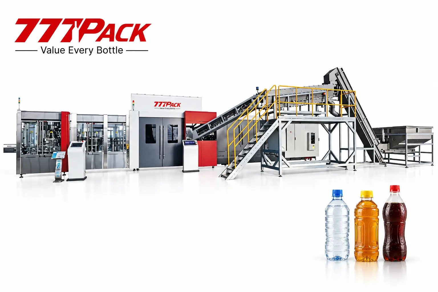
Combine PET bottle blowing, filling and capping in one coordinated rotary system. Select a configuration for your water, juice or carbonated beverage project, with four catalog models rated from 18,000 to 36,000 BPH at 500 mL.
Line integration
Position in the Production Line
The integrated blowing, filling and capping stage is highlighted below.
Swipe or scroll to explore all stages →
Water-line reference flow. Juice projects add product preparation and the selected thermal process; carbonated projects add product preparation and carbonation, with bottle warming where required. Final equipment scope follows the agreed product and process.
What Does a Combi-Block Do?
A blow-fill-cap combi-block starts with PET preforms and delivers filled, capped bottles. The blowing unit forms the container, the filling section receives the bottle directly, and the capping section closes it before discharge to the downstream conveyor.
Combining these processes shortens the transfer path between the blower and filler and brings their operating speeds into one coordinated system. Model selection starts with your required bottle formats, target output and beverage process.
Water, juice and carbonated beverage projects use different filling arrangements. 777Pack reviews the product, filling temperature, carbonation requirements, preform, bottle and cap together to define the appropriate configuration.
- Rotary blowing, filling and capping within one integrated system
- 8, 10, 12 or 16 blowing cavities
- Four catalog configurations with a 500 mL production reference
- Equipment layout and utilities matched to the selected model
- Downstream integration for coding, labeling, packing and palletizing
Machine Details
Explore the rotary transfer, filling and bottle-handling assemblies.
Integrated Rotary Transfer
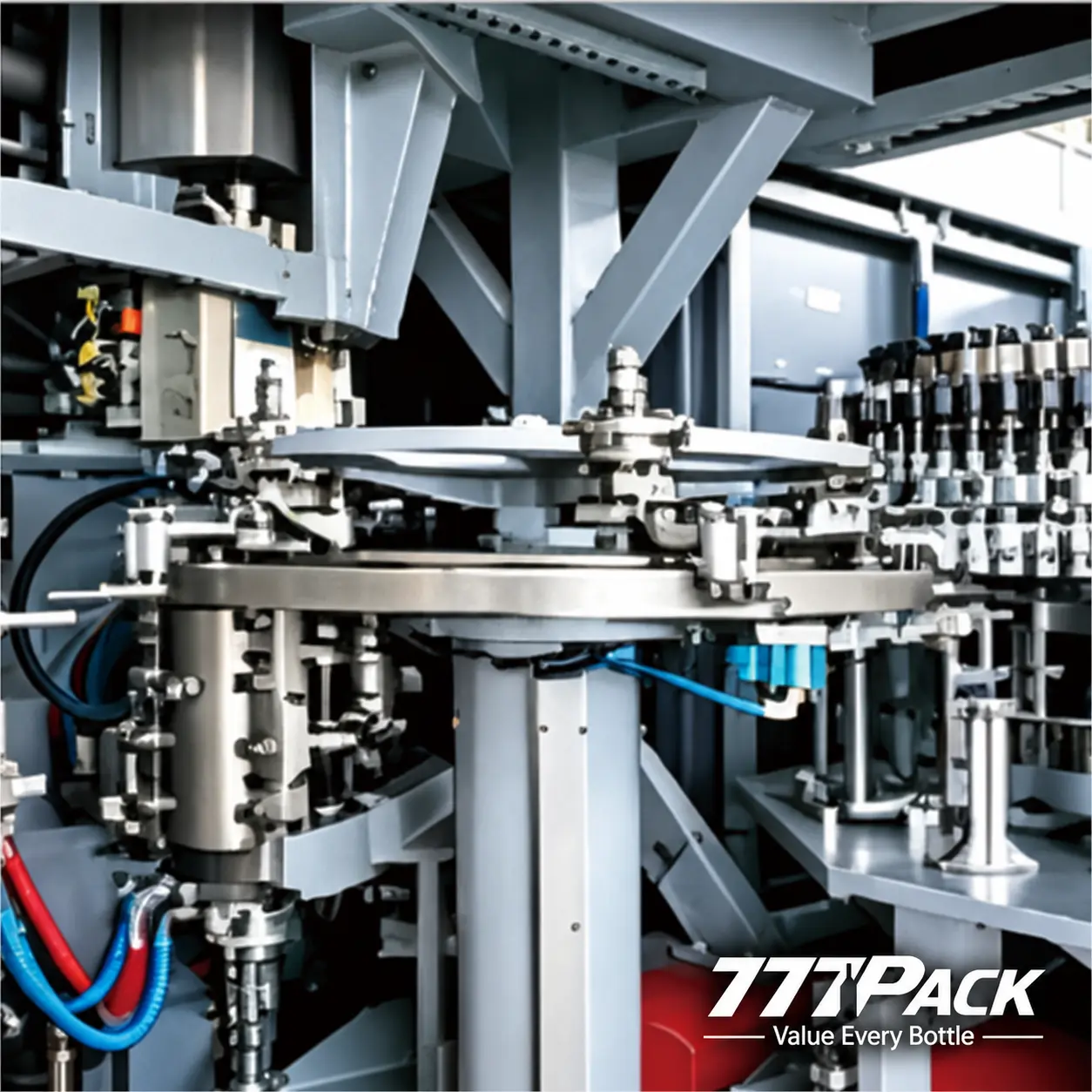
The transfer assemblies connect bottle forming with the filling and capping sections. Bottle geometry and neck finish guide the selection of compatible handling and change parts.
Product-Matched Filling
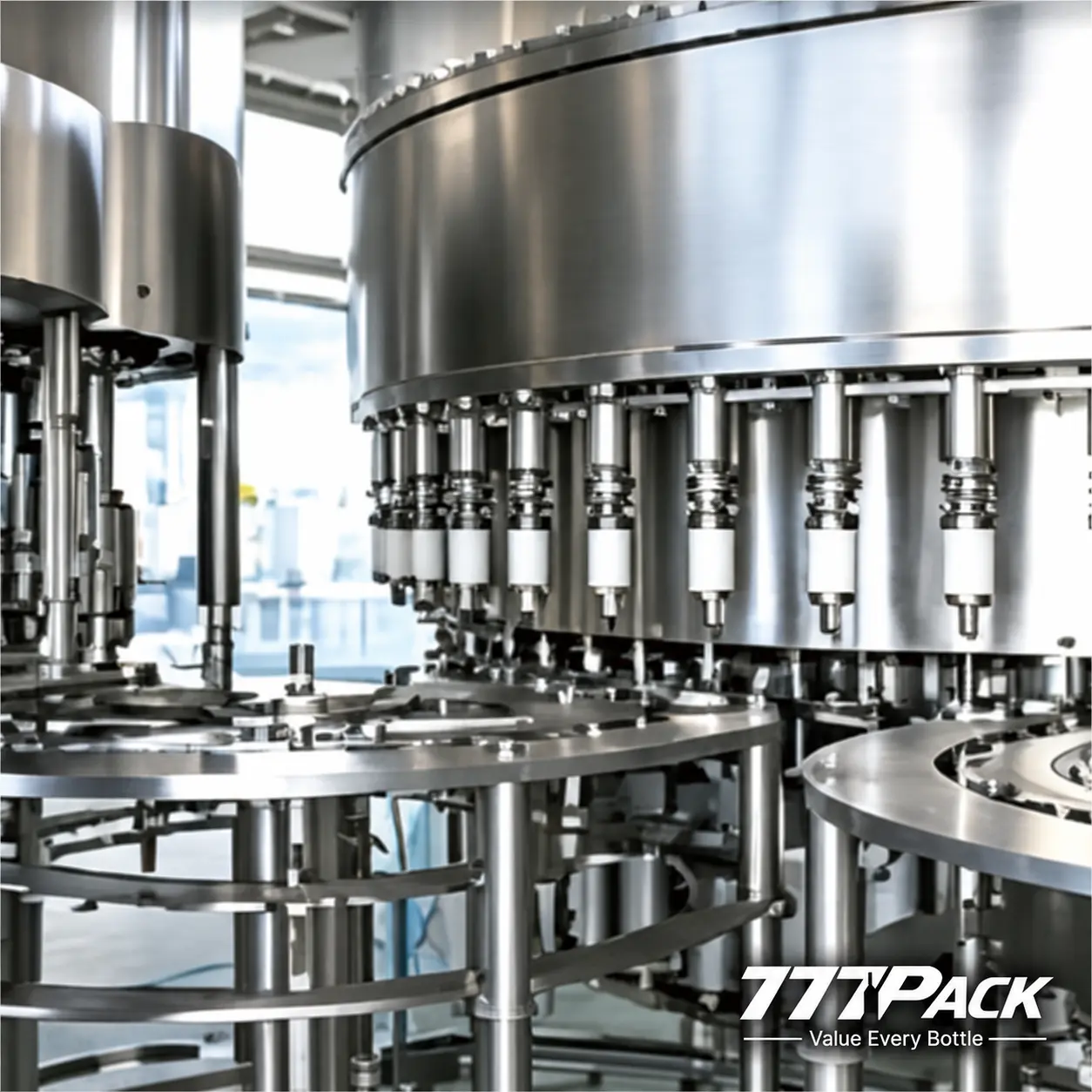
The rotary filling section is selected around the beverage and operating conditions. Filling temperature, carbonation and required output are reviewed during configuration.
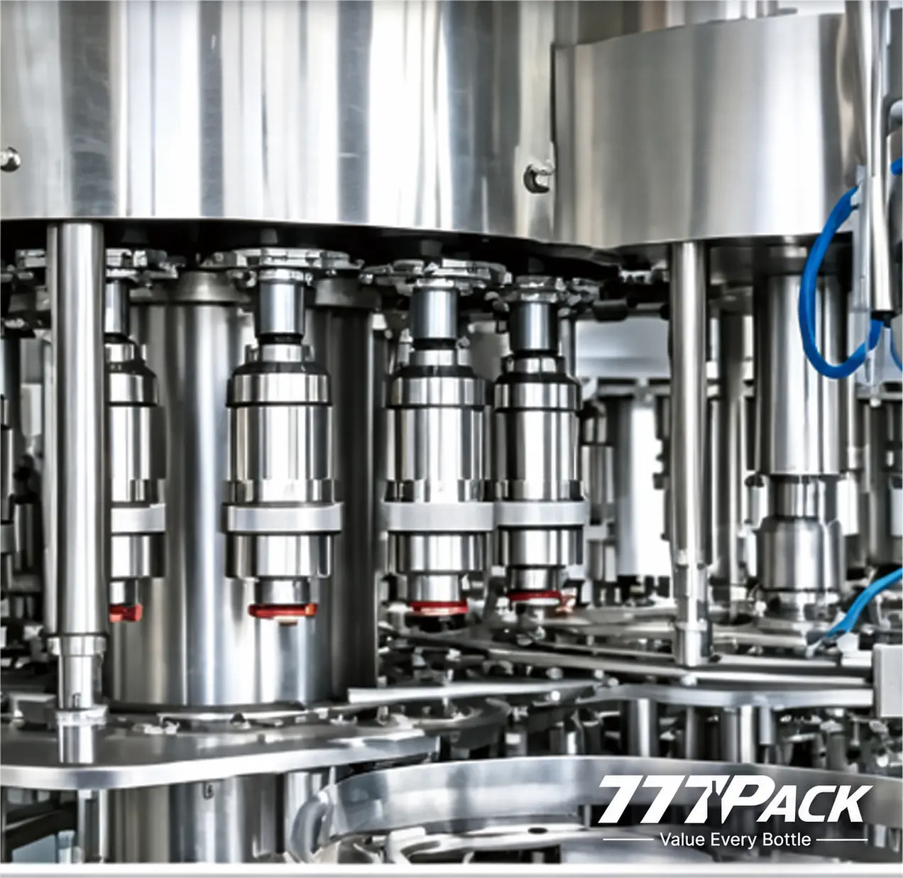
Bottle and Closure Coordination
Bottle transfer and closure application are matched to the approved neck finish and cap. Bottle and cap samples support configuration and acceptance planning.
Component References
Catalog component references; final brands and component scope are confirmed in the project configuration.
- Servo motor and drive
- Bosch Rexroth
- PLC
- Siemens
- Gear reducer
- SEW-EURODRIVE
- Variable-frequency drive
- Danfoss
- Low-pressure pneumatic components
- Festo
- High-pressure solenoid valves
- Seitz
- Electrical components
- Schneider Electric
- Static elimination
- Meech
Technical Specifications
Core bottle-format and electrical references for model selection.
| Parameter | Catalog reference |
|---|---|
| Process | PET bottle blowing + filling + capping |
| Rated capacity reference | 18,000–36,000 BPH, based on 500 mL bottles |
| Blowing cavities | 8–16, by model |
| Filling / capping heads | 32 / 10 to 60 / 22, by model |
| Maximum bottle volume — blowing unit | 2.5 L |
| Bottle diameter — filling unit | 50–100 mm |
| Bottle height — filling unit | 150–330 mm |
| Maximum preform height | 145 mm |
| Maximum bottle-neck diameter — blowing unit | 30 mm |
| Electrical supply — main catalog | 380 V, 50 Hz, 3PH + N + PE |
| Auxiliary / control voltage | 24 V DC |
Catalog reference values are based on 500 mL bottles. Maximum bottle volume is a blowing-unit limit; the approved bottle must also fit the filling section. Actual output follows the selected bottle, product, closure and operating conditions.
Available Models
Compare four configurations and their principal utility requirements.
| Model | Rated output (BPH · 500 mL) | Blowing cavities | Filling / capping heads | Max. bottle volume* (L) | Filling bottle diameter (mm) | Filling bottle height (mm) | Equipment envelope L × W × H (mm) |
|---|---|---|---|---|---|---|---|
| CGX8-32-10 | 18,000 | 8 | 32 / 10 | 2.5 | 50–100 | 150–330 | 12,300 × 7,300 × 4,100 |
| CGX10-40-15 | 24,000 | 10 | 40 / 15 | 2.5 | 50–100 | 150–330 | 14,100 × 8,400 × 4,300 |
| CGX12-50-18 | 28,000 | 12 | 50 / 18 | 2.5 | 50–100 | 150–330 | 14,100 × 8,400 × 4,300 |
| CGX16-60-22 | 36,000 | 16 | 60 / 22 | 2.5 | 50–100 | 150–330 | 15,600 × 9,600 × 4,500 |
*Maximum bottle volume refers to the blowing unit. Equipment dimensions include the host machine, heating furnace and hoist; the final layout also needs agreed access and service clearances.
Utilities by Model
| Model | Installed power (kW) | Average power consumption (kW) | Blowing air at 30 bar (m³/min) | Chiller catalog pair (HP) | Main cable section (mm²) |
|---|---|---|---|---|---|
| CGX8-32-10 | 170 | 60 | 6.3 | 10+15 | 95 |
| CGX10-40-15 | 180 | 80 | 8.4 | 12+15 | 120 |
| CGX12-50-18 | 200 | 94 | 9.8 | 12+15 | 150 |
| CGX16-60-22 | 220 | 120 | 12.6 | 15+20 | 185 |
Average consumption is the catalog reference, not a guaranteed measured value for every format. The paired chiller ratings are reproduced as listed for mold-bottom and oil-temperature cooling; circuit allocation is confirmed during utility planning.
Shared Utility Reference
| Parameter | Catalog reference |
|---|---|
| Actuation compressed air | 7 bar; 1 μm filtration |
| Blowing compressed air | 30 bar; 0.1 μm filtration; oil-free |
| Mold-bottom cooling inlet | 12 °C; 3–5 bar |
| Mold-body water / oil inlet | 25 °C; 3–5 bar |
| Filling-section air supply | 0.7 MPa; catalog gas consumption 0.8 m³/min |
| Filling-section electrical reference | 380 V AC (50/60 Hz), with 24 V DC control |
Agree the electrical frequency, air reference conditions, cooling circuit design and equipment inclusions in the final utility schedule.
How the Machine Works
From PET preform to filled, capped bottle.
Preform Feeding
Preforms enter the heating system, where the body is prepared for stretch blow molding.
Rotary Bottle Blowing
The selected 8–16 cavity configuration forms PET bottles from the approved preforms and bottle molds.
Direct Transfer
The formed bottles pass through the integrated transfer arrangement to the filling section.
Filling and Capping
The selected filling process introduces the beverage, then the compatible closure is applied.
Bottle Discharge
Filled and capped bottles leave for the agreed thermal treatment, drying, coding, labeling and secondary packaging stages.
Engineering Highlights
Configuration choices that connect the machine with your product and line.
Integrated Three-Process Layout
Blowing, filling and capping share a coordinated layout, shortening the transfer path between the bottle-forming and filling sections.
Rotary Output Selection
Choose from four model configurations with 8–16 blowing cavities and rated 500 mL outputs of 18,000–36,000 BPH.
Bottle and Preform Matching
Bottle diameter, height, neck finish and preform geometry are reviewed together, including the different blowing and filling limits.
Product-Based Configuration
Water, juice and carbonated projects are configured around the required filling process, temperature, product properties and closure.
Defined Utility Planning
The catalog provides model-specific power, blowing-air and cooling references to support site and auxiliary-equipment planning.
Complete-Line Coordination
Match the combi-block discharge to the selected drying, coding, labeling, packing and palletizing equipment.
Line Integration
Plan upstream preparation and downstream packaging around the combi-block.
The combi-block occupies the combined bottle-forming, filling and capping stage of a PET beverage line. Preforms and caps feed the machine, while the prepared product and utilities connect to the selected production configuration. Filled, capped bottles pass to the downstream line.
Before the combi-block
Prepare the required process water or beverage, preforms, caps, compressed air, cooling and electrical supply.
After the combi-block
Match any product-specific cooling or warming stage, then drying, coding, labeling, packing and palletizing.
Line interfaces
Review target output, conveyor arrangement, accumulation, machine signals and the available factory layout.
Water Lines
Coordinate water treatment with integrated PET bottle forming, filling and capping, followed by downstream packaging.
View water line solutions →Juice Lines
Select beverage preparation and the agreed filling-temperature and thermal-treatment route for the intended juice product.
View juice line solutions →Carbonated Beverage Lines
Plan beverage preparation, carbonation and the corresponding filling configuration, with downstream bottle warming where required.
View carbonated line solutions →Configuration and Delivery Scope
Define the complete equipment and service package for your project.
- Selected CGX model with rotary blowing, filling and capping
- Heating-system and preform-feeding arrangement
- Approved bottle molds, preforms, neck finishes and caps
- Filling process matched to the intended beverage
- Electrical, compressed-air and cooling connections
- Control and component configuration
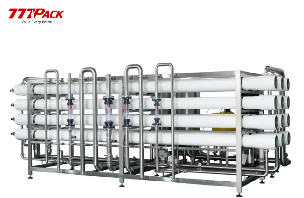
- Water treatment and beverage preparation equipment
- Compressed-air and cooling equipment
- Product-specific cooling, warming or other thermal stages
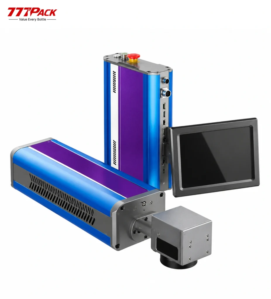
- Coding, labeling, secondary packaging and palletizing
- Factory layout, installation and commissioning scope
- Acceptance testing, operator training, spares and after-sale support
The quotation defines the supplied equipment, utilities, testing and service scope. Review pre-sale engineering support →
Frequently Asked Questions
Practical questions about output, compatibility and project planning.
What is a Blow-Fill-Cap Combi-Block?
It is an integrated PET bottling system that forms bottles from preforms, fills the selected beverage and applies the closure. The blowing, filling and capping sections operate as one coordinated machine arrangement.
What is the capacity of this model series?
The four catalog models are rated at 18,000, 24,000, 28,000 and 36,000 bottles per hour, based on 500 mL bottles. Bottle design, beverage process, cap specification and utilities determine the agreed project output.
Can the system be configured for water, juice and carbonated drinks?
Yes, the project configuration is selected for the intended beverage. Filling technology, temperature, carbonation requirements and cleaning arrangements are reviewed for that product; the catalog table does not mean that one standard configuration handles every beverage process.
What PET bottle sizes can be considered?
The four published configurations have a catalog maximum blowing volume of 2.5 L. Filling-section limits are 50–100 mm in bottle diameter and 150–330 mm in bottle height. Bottle and preform drawings are needed to confirm a specific format.
What information is needed before selecting a model?
Provide the beverage type, target output for each bottle size, bottle and preform drawings, neck finish, cap samples, filling temperature and any carbonation requirements. A factory floor plan and available utilities help define the complete arrangement.
How can the combi-block connect to a complete production line?
777Pack reviews product supply, preform and cap feeding, utilities, downstream conveyors and packaging speeds together. The final line can include water treatment or beverage preparation, drying, coding, labeling, film wrapping or other secondary packaging, and palletizing.
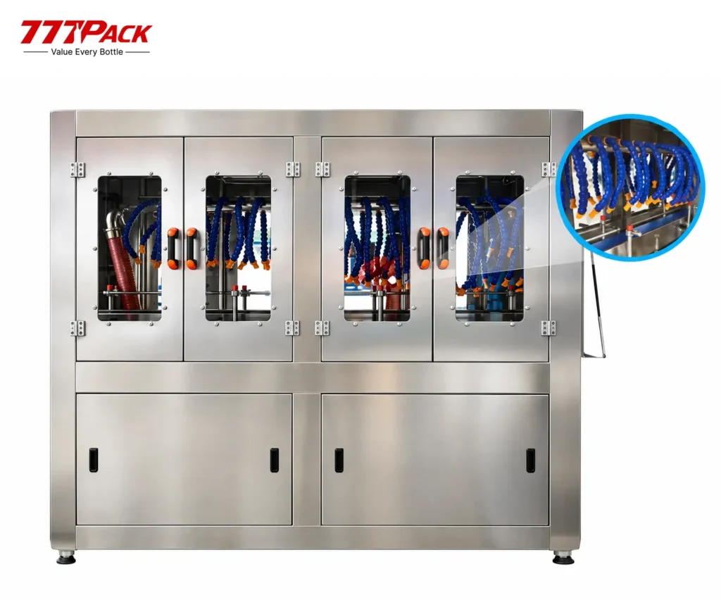
Related Equipment and Project Reference
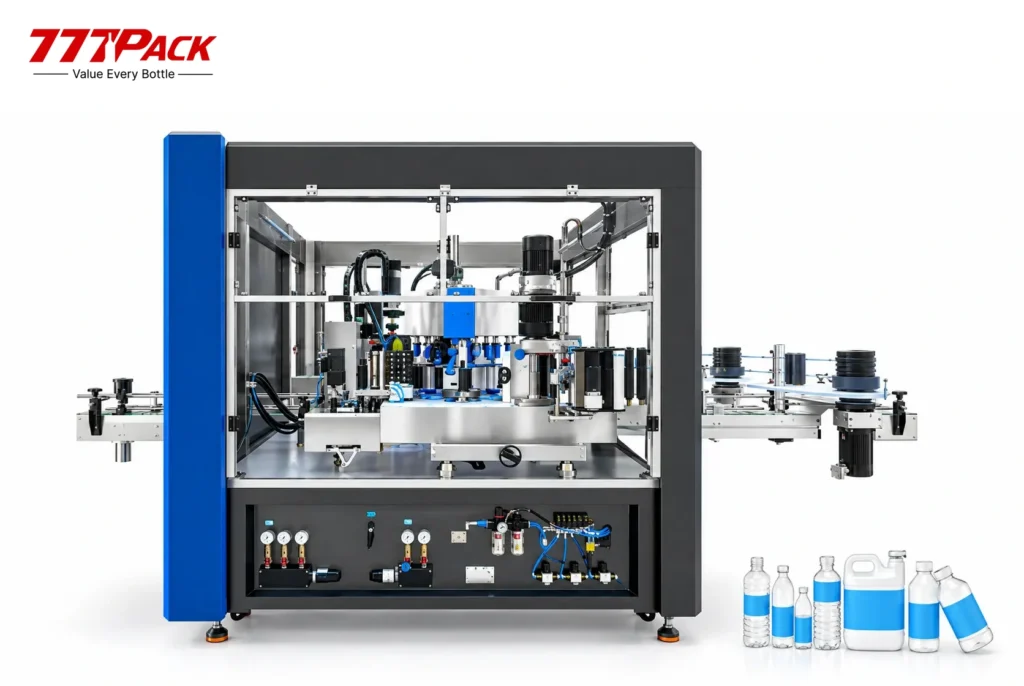
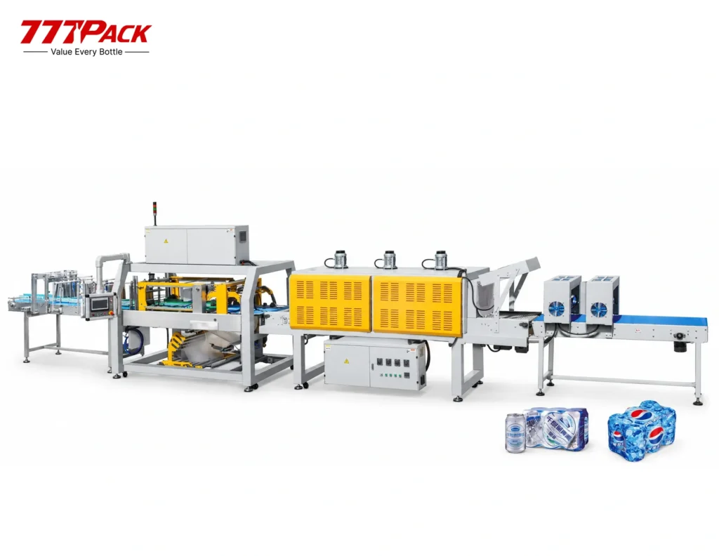
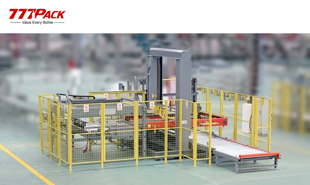
Explore the machines in the process flow, from water treatment to palletizing, and review an installed combi-block line.
02 · Current equipment: Blow-Fill-Cap Combi-Block ↑
Project Evidence
33,000 BPH Bottled Water Line in Bandung
Review the delivered combi-block water-line project, including its process arrangement and downstream packaging equipment.
View the Bandung combi-block project →Plan Your PET Beverage Line
Configure your Blow-Fill-Cap Combi-Block
Share your beverage, bottle and preform drawings, cap specification, target output and factory layout. 777Pack will review the model, filling process, utilities and complete-line connections.