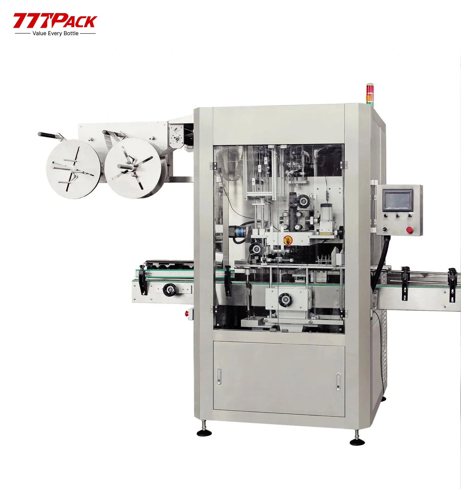
Shown: SLM-350B single-head applicator.
Single-Head Shrink Sleeve Labeling Machine
Models:SLM-150B · SLM-250B · SLM-350B
One head for bottle-body shrink sleeves. Compare three model configurations with servo feeding and cutting, then match the applicator with its steam shrink tunnel.
Rated maximum output is model-dependent and varies with the bottle and sleeve. Bottle material and geometry are confirmed with samples.
Line integration
Position in the Production Line
Labeling is the current stage in this PET water-line example. Sleeve application and steam shrinking form one labeling system.
Swipe or scroll to explore all stages →
Reference flow only. The PET bottle shown is an example application, not a universal bottle-material specification. Confirm bottle samples, sleeve film, shrinking conditions and the final equipment sequence for the project.
Equipment Overview
Apply one shrink sleeve to the bottle body, then finish the package through a matched steam tunnel. The three single-head models provide different output, bottle-diameter, sleeve-length and electrical configurations.
Model selection starts with the actual bottle and sleeve, rather than speed alone. Review the film, sleeve dimensions, bottle stability, available conveyor time and steam package together.
Explore the sleeve labeling category or compare the double-head shrink sleeve labeling machine for a different head arrangement.
Choose the Sleeve Configuration
Match the sleeve position first, then compare model output and format limits.
One Head · Bottle-Body Sleeves
SLM-150B · SLM-250B · SLM-350B
One sleeve application head for the bottle body. Compare the model-specific format limits, rated output and steam package below.
For body and neck / mouth-area sleeves, review the SLM-150D / SLM-250D double-head configuration.
Model Comparison
Available Models & Technical Comparison
Compare each model as its own configuration; format ranges and electrical arrangements differ.
| Parameter | SLM-150B | SLM-250B | SLM-350B |
|---|---|---|---|
| Sleeve position | Bottle body | Bottle body | Bottle body |
| Heads | 1 | 1 | 1 |
| Rated maximum output | 9,000 BPH | 15,000 BPH | 21,000 BPH 100 mm sleeve reference |
| Bottle-body diameter | 28–125 mm | 28–120 mm | 35–120 mm |
| Sleeve length | 30–250 mm | 30–250 mm | 10–300 mm |
| Film thickness | 0.03–0.13 mm | 0.03–0.13 mm | 0.03–0.1 mm |
| Sleeve film | PVC · PET · OPS | PVC · PET · OPS | PVC · PET · OPS |
| Host input power | 3.5 kW | 3 kW | 5 kW |
| Host dimensions, L × W × H | 2,000 × 1,200 × 2,070 mm | 2,000 × 1,200 × 2,070 mm | To be confirmed for selected model |
| Host electrical supply | 220 V AC; phase/frequency to be confirmed | To be confirmed for selected model | 220 V AC, single-phase, 50/60 Hz |
| PLC / HMI | Siemens 40T / SMART | Siemens 60T / SMART | Siemens / Siemens |
| Servo configuration | INOVANCE feed/cut servo; 400 W specified | INOVANCE: 750 W feed + 400 W cutting | INOVANCE; rating to be confirmed for selected model |
| Frequency converters | Siemens | Siemens | Siemens |
| Sensors | Panasonic | Panasonic | Panasonic |
| Host construction | SS304 and aluminum alloy | SS304 and aluminum alloy | To be confirmed for selected model |
Rated figures are maximum model references, not a promise for every sleeve and bottle. SLM-350B is rated at a 100 mm sleeve. Host input power is separate from the steam-generator and tunnel loads. Dimensions and supply are confirmed in the selected equipment specification.
Core Specifications
Bottle and sleeve samples define the final application. PET, PVC and OPS above identify sleeve films, not bottle materials.
| Head arrangement | Single-head bottle-body application |
|---|---|
| Model range | SLM-150B · SLM-250B · SLM-350B |
| Rated model output | 9,000–21,000 BPH; see the model-specific reference conditions |
| Sleeve materials | PVC, PET and OPS shrink films |
| Bottle material | Confirmed against the selected model and actual bottle samples |
| Bottle geometry | Diameter, body shape, neck finish and stability reviewed for the application |
| Sleeve dimensions | Model-specific sleeve length and film-thickness limits |
| Application mechanism | Servo-controlled sleeve feeding, cutting and application |
| Control system | PLC, touchscreen HMI, servo drive and frequency converters; brands depend on model |
| Shrinking | Downstream steam shrink tunnel |
| Steam arrangement | Separate steam-generator load and model-specific tunnel duty |
| Line interfaces | Conveyor transfer, bottle spacing, line speed and downstream handling confirmed for the project |
Working Principle
- 01
Container Infeed
Guide and space bottles through the applicator in the selected conveyor arrangement.
- 02
Sleeve Feeding
Feed the sleeve film and maintain the required positioning and tension for the selected format.
- 03
Servo Cutting
Cut the sleeve to the selected length using the servo-driven mechanism.
- 04
Sleeve Application
Apply the body sleeve in the single-head configuration.
- 05
Steam Shrinking
Pass the sleeved bottle through the matched tunnel with its steam-nozzle settings adjusted for the film and bottle.
- 06
Downstream Transfer
Check the finished sleeve and transfer bottles to the agreed downstream equipment.
This is a functional overview. Exact infeed, head layout, shrinking settings and inspection points follow the selected model and approved format.
Key Component Brands
Use the model table to distinguish the control and servo configurations.
The specified SLM-350B configuration includes Schneider switching components. Confirm the final bill of materials for the selected machine.
Engineering Selection
Match Film and Bottle
Confirm sleeve drawings, film specification, bottle samples and the target sleeve position before selecting format parts.
Compare the Model Conditions
Review the rated output with sleeve length, bottle geometry and the available line time. Use the model-specific reference conditions.
Adjust the Steam Sections
The tunnel uses three individually adjustable steam-nozzle sections for height, position and output. Set the process for the approved bottle and film.
Plan Transfers and Access
Review bottle spacing, conveyor handovers, steam connections, condensate collection and access for format changes and maintenance.
Steam Tunnel & Utilities
Tunnel duty and generator capacity vary with the selected model.
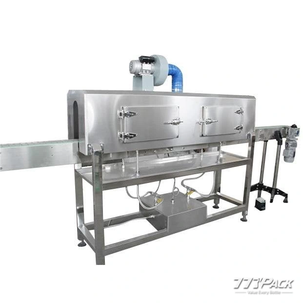
Match the applicator with its steam shrink tunnel and electric steam generator. Plan these units together while keeping their connected loads and steam duties separate.
The stainless-steel tunnel includes insulation and condensate collection. Three nozzle sections allow the steam position, height and output to be adjusted for the selected sleeve and bottle.
Steam Package by Model
| Parameter | SLM-150B | SLM-250B | SLM-350B |
|---|---|---|---|
| Tunnel dimensions, L × W × H | 1,800 × 600 × 1,600 mm | 1,800 × 600 × 1,600 mm | 2,300 × 600 × 1,600 mm |
| Tunnel working steam pressure | 0.1 MPa | 0.1 MPa | 0.2 MPa |
| Tunnel steam consumption | 10–20 kg/h | 10–20 kg/h | To be confirmed for selected model |
| Tunnel blower load | 250 W | 250 W | 200 W |
| Generator input power | 18 kW | 24 kW | 36 kW |
| Generator steam output | 18 kg/h | 20 kg/h | To be confirmed for selected model |
| Generator steam pressure | 0.25–0.4 MPa | 0.25–0.4 MPa | 0.7 MPa |
These are separate unit ratings. Confirm the final electrical supply for each unit, steam connections, operating settings, drainage and installation arrangement. Do not use the host input power as the complete system load.
Separate the Loads
Review the applicator, tunnel blower, conveyor and steam-generator supply with the final electrical specification.
Confirm the Connections
Review generator feedwater, steam delivery, condensate collection and the drainage route for the installation.
Reserve Working Access
Approve the equipment footprints, conveyor elevations and space for operation, cleaning and format changes.
Define the Package
Confirm the included applicator, shrink tunnel, steam generator, conveyor sections and interface responsibilities in the proposed configuration.
Bottle & Sleeve Compatibility
Specify the bottle material, shape, body diameter, neck finish, height and filled condition. The actual container must be assessed with its sleeve and the intended shrinking process.
PVC, PET and OPS are supported sleeve-film materials in the listed configurations. They do not define bottle-material compatibility. Review shrink behavior, artwork registration, sleeve length and film thickness for each format.
Round and square bottle formats can be reviewed for SLM-150B / SLM-250B. Other geometries, neck features and change parts are reviewed against the selected model and actual samples.
Approve the finished sleeve appearance and handling using representative bottles and production sleeve rolls before acceptance.
Line Integration
The reference water line places sleeve labeling after coding and before secondary packaging. Confirm the actual coding and sleeve sequence for the artwork and package.
Review the infeed and outfeed with the conveyor system, including bottle spacing, transfer height, line speed and machine start/stop coordination. Where the upstream process leaves water on the bottle, review bottle air drying for the required surface condition.
Coordinate the labeler with the filling equipment and downstream packing. Our pre-sale engineering review can define the handovers and selected equipment scope.
Testing & Acceptance
Approve the Formats
Use representative bottle samples, body sleeve drawings and production film rolls for the selected model.
Check Output and Transfers
Run the agreed bottle and sleeve at the required output while checking spacing, application, shrinking and downstream transfer.
Agree the Inspection Points
Review sleeve position, cut length, artwork registration and shrink finish against the approved sample.
Record the Settings
Confirm format settings, operating guidance, cleaning access and any change parts required for the approved range.
Frequently Asked Questions
What does single-head mean for this range?
SLM-150B, SLM-250B and SLM-350B are single-head bottle-body sleeve applicators. The shrink tunnel finishes the sleeve after application.
How do the three models differ?
Compare rated output, bottle-body diameter, sleeve dimensions, host power, control details and steam package. The model table keeps these differences separate.
Which sleeve materials are listed?
The configurations list PVC, PET and OPS shrink films. Select the film with the required shrink behavior, artwork and bottle. These film names do not establish bottle-material compatibility.
How does sleeve format affect output?
Actual output depends on the bottle, sleeve length and selected arrangement. The SLM-350B reference is 21,000 BPH with a 100 mm sleeve. Review your actual format before choosing a model.
Which bottle shapes and materials can be used?
Provide bottle samples or drawings, including body diameter, shape, neck finish and material. Review round and square formats with the SLM-150B / SLM-250B selection, including the actual samples and format parts.
What sleeve-roll information is needed?
Provide film type, thickness, sleeve length, roll width, core details and roll dimensions. Roll compatibility is confirmed with the selected application and sample roll.
What does the steam package require?
Plan the tunnel and generator separately from the applicator. Confirm their electrical supplies, steam duty, feedwater, condensate collection, drainage and final installation layout.
Is the host power the complete system load?
No. The listed host power excludes the separate steam-generator and tunnel blower loads. Use the final equipment specification to define the installation load.
How does it connect to the production line?
Confirm bottle spacing, conveyor transfer height, line speed and the downstream packing handover. Review the conveyor equipment with the complete line.
When should I review a double-head model?
For body and neck / mouth-area sleeves, review SLM-150D / SLM-250D. For the dual-head body configuration at higher rated output, compare SLM-400BD / SLM-500BD on the double-head shrink sleeve labeling page.
Project Services
Manufacturing & Line Integration
Core equipment manufacturing, auxiliary-machine coordination and complete-line integration are managed as one system to reduce interface risks before delivery.
FAT & Quality Inspection
Project checks before packing and delivery.
Installation & Commissioning
On-site setup, testing and operator training.
Local Support in Indonesia
Local coordination for service and spare parts.
Match the Sleeve System to Your Bottle
Send bottle samples or drawings, sleeve positions, film details, required output and the factory layout.